
Airfoil Optimization Essentials
Airfoil optimization is a classic problem in aerodynamic design – long tackled through a variety of approaches. Vortex features an optimization framework powered by Automatic Differentiation (AD), giving designers the flexibility needed to generate performant and robust airfoil geometries in a fraction of the time required by conventional optimizers.
Problem SetUp
There is no single universal way to formulate an aerodynamic optimization problem. However, mastering a few core concepts makes it possible to tailor setups to your exact physical and operational demands.
Objectives
Objectives define the quantitative measure of merit used to evaluate candidate designs. A problem may have one or multiple objectives, often with conflicting goals that force the optimizer to find a balanced design (compromise solution).
Typical aerodynamic objectives include:
- Minimize drag
- Maximize lift
- Maximize aerodynamic efficiency (Lift / Drag)
Objectives must be paired with explicit operating conditions—such as a target lift coefficient (), angle of attack (), or flap deflection (). Defining these operating points is an essential part of the objective formulation, ensuring the optimization reflects the airfoil’s true operational envelope and mission requirements.
Geometric Constraints
Geometric constraints enforce physical and structural boundaries on the airfoil, ensuring generated profiles are both manufacturable and structurally viable.
Typical constraints may include:
- thickness to chord ratio (tc)
- trailing-edge thickness
- Section Inertia (Ixx)
- Section Modulus (SMx)
When formulating an optimization problem, it is important to remember that aerodynamic gains are easily bought at the expense of structural integrity. For example, relaxing section inertia relative to a reference profile will reduce drag, but will yields a highly flexible wing in a 3D structural analysis. Similarly, omitting section modulus constraints may lead to unacceptably high bending stresses under load.
Aerodynamic Constraints
This is where much of the optimization magic comes into play. While objectives measure what we strive to maximize, aerodynamic constraints dictate how the airfoil must perform across the rest of the flight envelope. They allow us to enforce performance boundaries at off-design conditions—such as takeoff, loiter, and landing. Aero constraints are also a convenient way to force the optimizer to converge into robust designs.
Typical aerodynamic constraints include:
- Max Cl
- bounds of the drag bucket
- pitching-moment
- lift slope
- cavitation inception.
These may be evaluated in any operating condition.
Airfoil Robustness
Left unchecked, an optimizer will inevitably find ways to “cheat” the problem —delivering a profile with exceptional performance at the exact objective point, with catastrophic degradation under perturbed conditions. This pitfall, known as over-optimization, creates airfoils that look impressive on paper but fail in real-world uncertain operating environments. Selecting appropriate geometric and aerodynamic constraints prevents the optimizer from exploiting these artificial shortcuts. Recognizing the “easy” geometric traits an optimizer tends to abuse usually comes with experience and practice.
Practical Case – Wingfoil Front Wing Section
Design Brief
We are going to design a section for the main wing of a hydrofoil. This wing currently has a NACA2412 section throughout the entire span. We are going to use this section as out reference/baseline.
The design brief is as follows:
- Area = 800cm2
- Chord = 10cm
- Takeoff Speed = 12kts
- Cruise Speed = 16kts
- Maximum Speed = 22 kts.
- Max Cl > Ref.
- Ixx > Ref
The objectives of this optimization are:
- Min Cd @ Cruise
- Min Cd @ Max Speed
Subject the this aerodynamic constraint:
- Cd @ Takeoff < Ref
Cl Calculations
The first step before we can optimize anything is deriving the Cls and Reynolds number of the airfoil in its operating conditions. We can input the surface, chord and speed data into the “Fluid Calculations” tool to easily derive the required properties.

We get the following Cls and Reynolds:
- Takeoff Cl = 0.56 / Re = 0.6M
- Cruise Cl = 0.31 / Re = 0.8M
- Max Speed Cl = 0.16 / Re = 1.1M
Optimization Sequence
We are going to optimize sequentially by adding objectives and constraints one at the time so we can understand how they impact the design. Additionally, you will see that we end up with a few more constraints that what we defined originally. This is expected and part fo the exploratory process of airfoil optimization in an attempt to achieved a robust solution.
In our first optimization run we are simply going to define the objectives

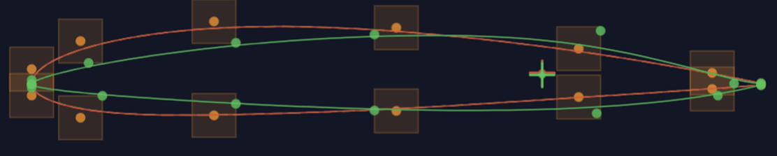
We can see that the section is thin and super pointy. This means that the section is “over-optimized”. We will now start adding constraints to mitigate steer away from this family of sections. We will start by adding the inertia constraint.

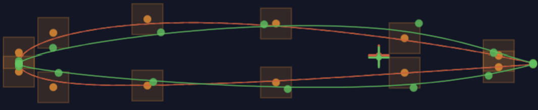
The Section continues to be super pointy but its gained some thickness to match the required inertia. We will continue by adding the main aerodynamic constraints from the problem definition


The new section has a much more noble leading-edge radius. However, its also pushing the location of maximum thickness very far aft in order to delay the transition point as much as possible. Therefore, we are going to add a new constraint in which we limit the Cd of the airfoil at maximum speed in a turbulent environment (Ncrit=0.1).


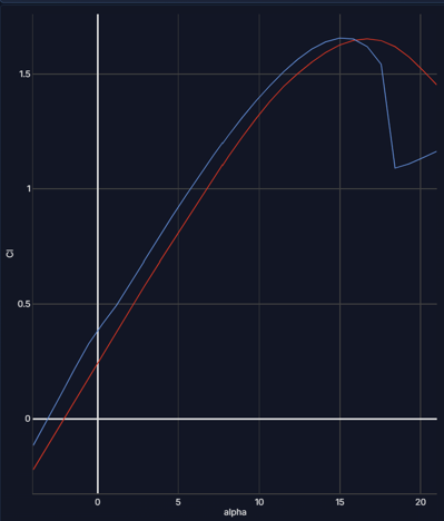
This last constraint has indeed flattened the aft region of the top surface of the profile making it more robust to an uncertain operating environment. However, observing the Cl graph this section has an abrupt stall, we can now add another Cl constraint to smooth it out.


Now a negative thickness issue towards trailing edge has appeared, so we add a thickness constraint towards the trailing edge to ensure positive thickness.

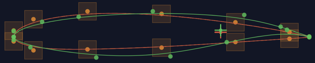
The Section is geometrically sound again, but its pushing the recovery zone very hard which increases the risk of separation; we can limit this by imposing a constraint on the maximum dCp.

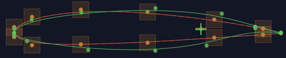
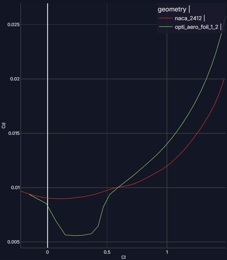
This last section looks great! However, looking at the graph we see that its drag spikies after the defined takeoff condition @ Cl=0.56. This is not necessarily bad as its outside our operating range, but just to make sure its robust to a wide range of conditions, we are going to add another constraint of Cd @ Cl=1.

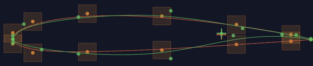
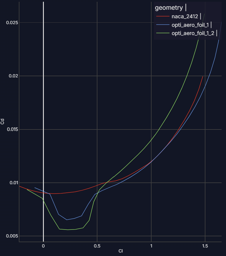
This new drag curve looks very gentle, with a good drag bucket but tiwhout a drag spike. Unfortunately the section looks a bit thin in the aft region and may be a bit brittle, so we add another geometric constraint to require some more thickness.


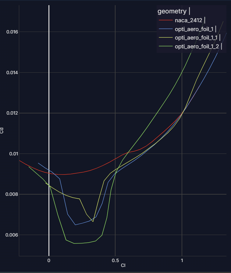
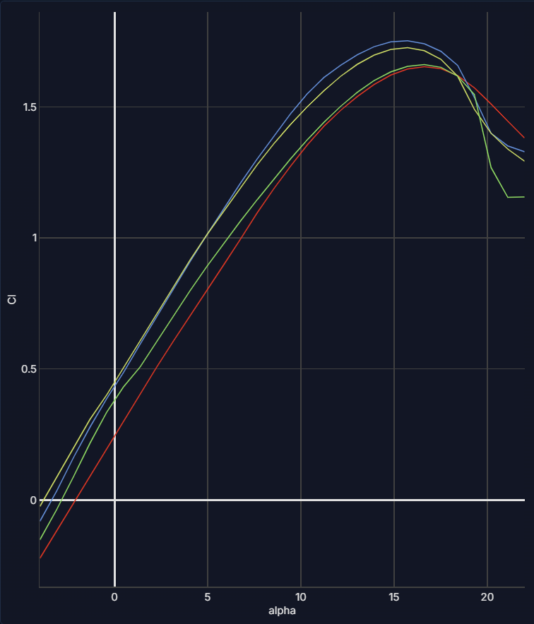
I think we finally have a nice looking airfoil that provides a nice drag improvement without sacrificing any of our initial requirements or converging into unrealistic shapes.
It is worth noting that there is no absolute “right” or “wrong” in airfoil optimization—neither in how a problem is formulated nor in the geometry produced. Every optimized profile is simply the exact answer to a specific set of questions. Because designers bring their own styles, preferences, and domain-specific insights, giving the same problem to N designers will inevitably yield N unique solutions.
I would encourage everyone to follow their own intuition and experiment freely. Optimization is as much an art as it is a science.