How to Design an Airfoil Section
A Conceptual Introduction
Introduction
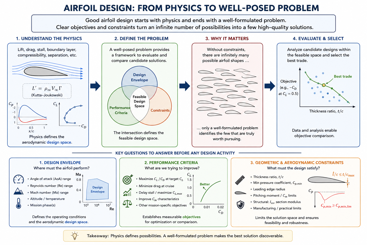
As with all engineering disciplines, airfoil design requires a strong understanding of the underlying physics, along with a clearly defined problem definition that includes measurable objectives and constraints. The former establishes the aerodynamic design space, while the latter provides a framework for analytically comparing candidates. Since unconstrained airfoil design admits an effectively infinite number of solutions, the quality of the final section depends heavily on how well the problem is formulated. Consequently, particular attention should be given to the following questions before beginning any design activity:
- Design envelope (AoA, Reynolds number, Mach number, etc.)
- Performance criteria (minCd, maxCl…)
- Geometric and aerodynamic constraints (t/c, Cp,min, Ixx, etc.)
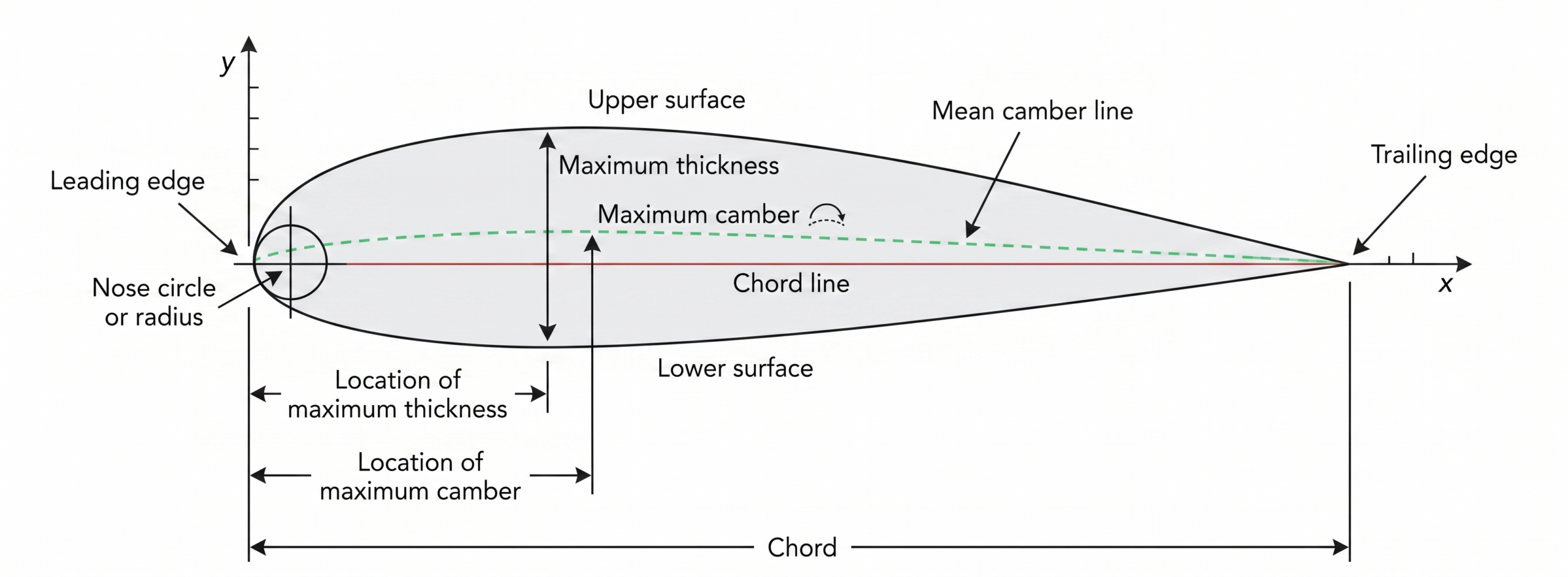
Foil Anatomy
It is important to know the basic anatomy of an airfoil so a common language can be shared between designers and software tools alike.
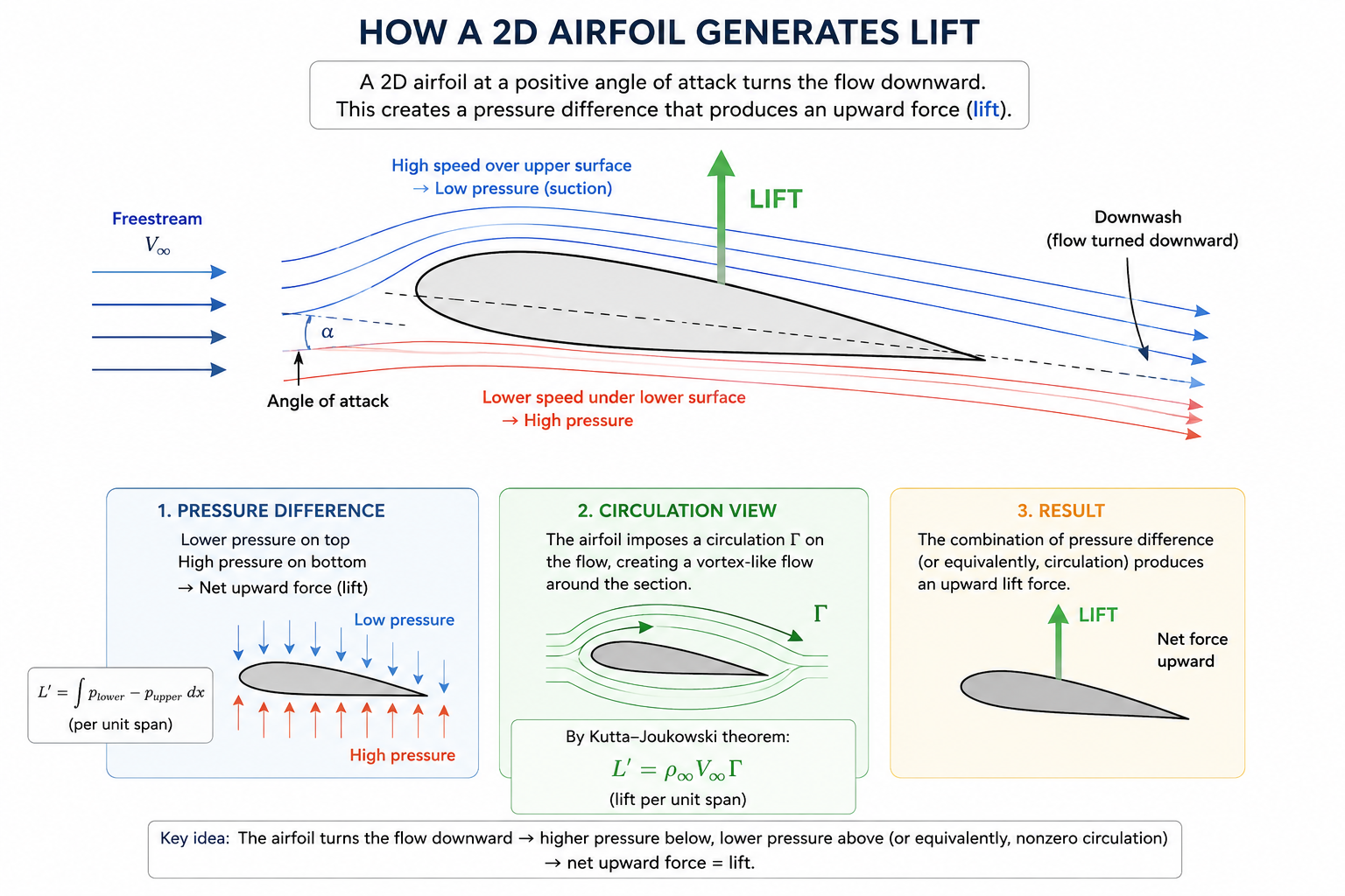
How is Lift Generated?
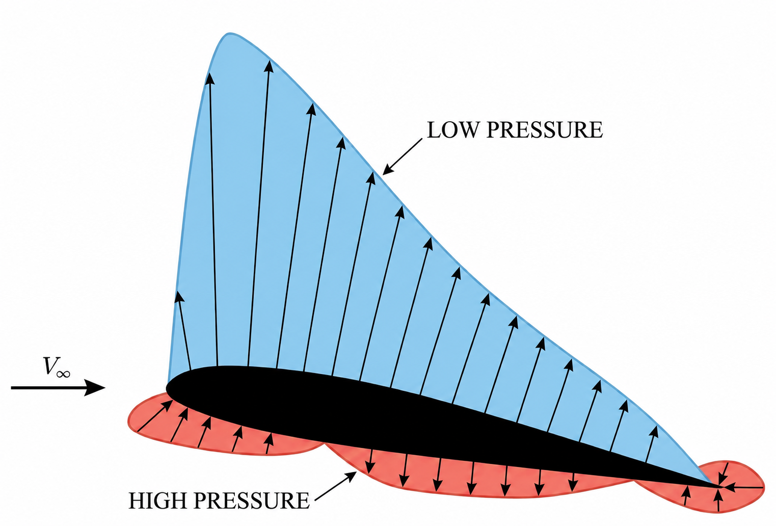
A 2D airfoil generates lift by turning the incoming freestream flow downward, producing an upward aerodynamic force in accordance with conservation of momentum. This flow turning is accompanied by a pressure distribution around the airfoil: for conventional airfoils, the flow accelerates over the curved upper surface, creating lower pressure relative to the lower surface and the surrounding flow. The resulting pressure difference produces a net upward force, commonly referred to as lift. From a fluid mechanics perspective, this lift arises because the airfoil induces circulation in the flow field, which modifies the velocity distribution around the section. According to the Kutta–Joukowski theorem, the lift per unit span is proportional to the freestream velocity, fluid density, and circulation strength.
Airfoil Pressure & Shear Distribution
The pressure and shear stress distributions along an airfoil’s chord ultimately determine its aerodynamic performance, since their integration over the surface yields the lift, drag, and pitching moment coefficients. In most cases, pressure forces are roughly two orders of magnitude larger than shear stresses, meaning that lift can often — though not always — be estimated reasonably well from pressure distributions alone. Drag, however, is far more sensitive to viscous effects, and shear stresses become especially important at low angles of attack, where skin-friction drag is typically the dominant contribution.
Lift Coefficient
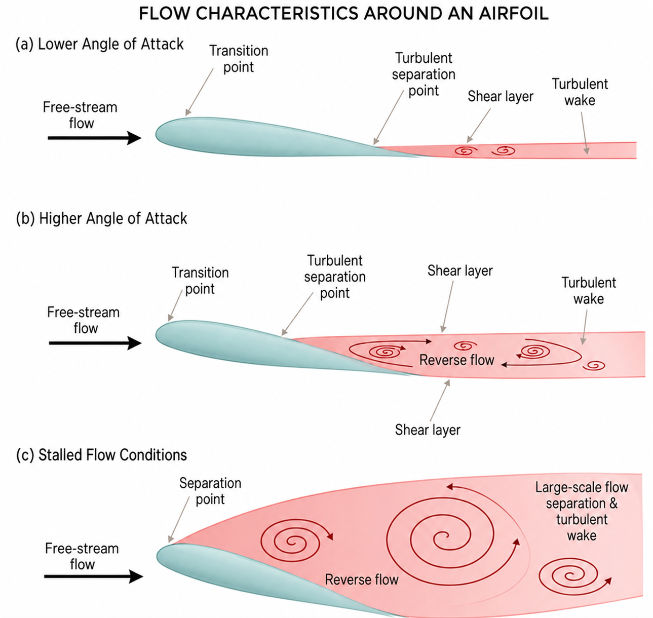
For small angles, the lift produced by an airfoil is directly proportional to its angle of attack, typically following a slope of 2pi. As the angle of attack increases, the boundary layer thickens (flow separates from the surface), and the aerodynamic characteristics start exhibiting nonlinear behaviour. At some point, a further increase in angle of attack does not yield a further increase in lift at a condition known as stall. At such point the airfoil has achieved its max lift coefficient.
The stall process and the achievable value of Cl depend on both the airfoil shape and the operating conditions, i.e., Reynolds and Mach numbers. Some airfoils, particularly those with greater thickness and camber, exhibit a gradual onset of stall, whereas others with sharp leading edges stall abruptly.
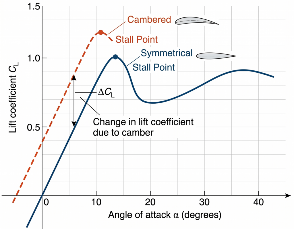
Asymmetric airfoils can generate higher values of lift at a greater efficiency than their symmetric counterparts. This is possible by sacrificing performance at negative angles of attack, which means they have a narrower effective operating window.
Flaps increase the effective camber of an airfoil. This shifts the lift curve to the left meaning that at any given angle of attack, the flapped airfoil produces more lift than the clean airfoil. For an ideal 2D airfoil, the slope of the lift curve remains the same. It must be noted that the stall angle is also reduced.
Drag Coefficient
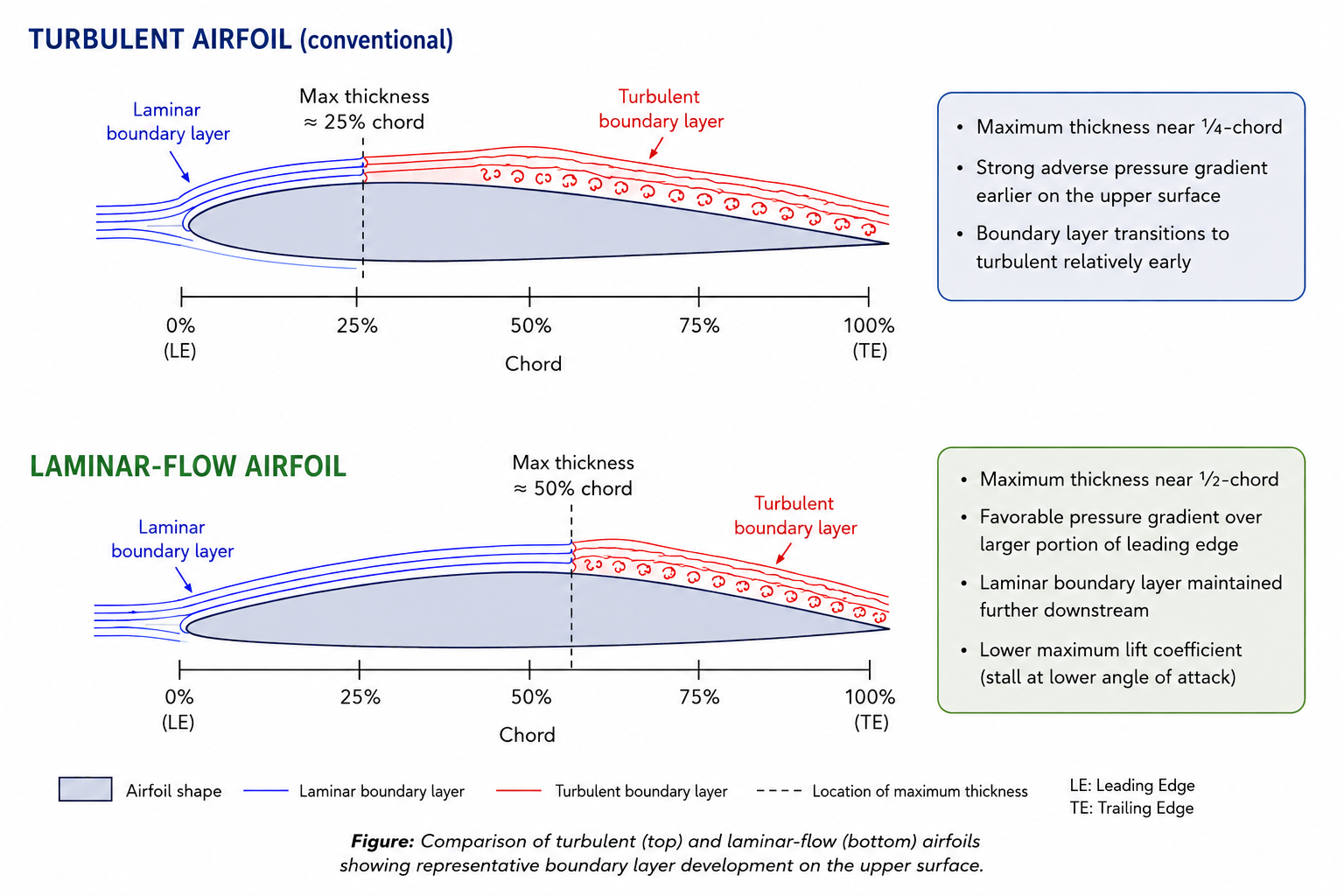
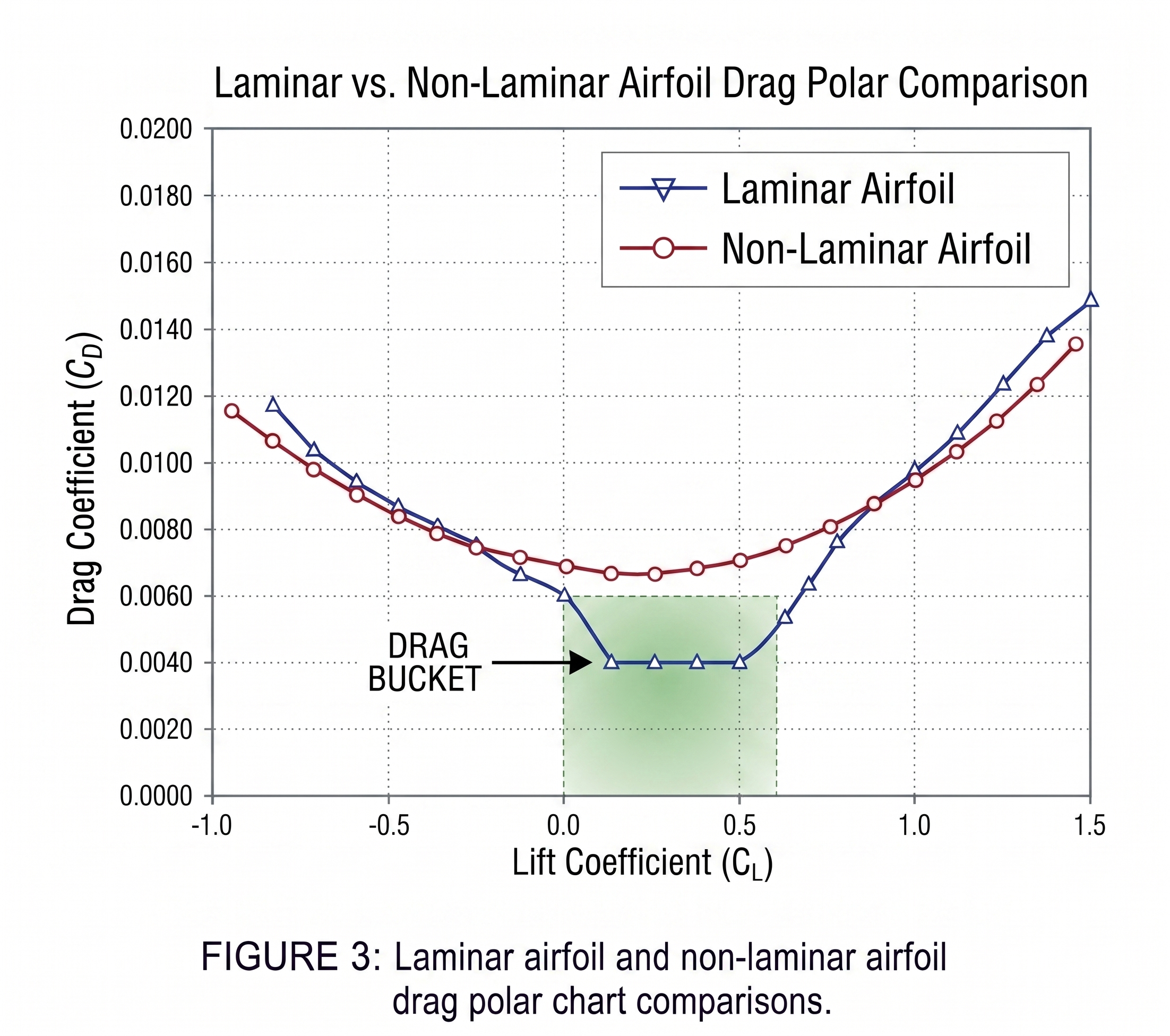
Depending on the shape of its drag polar, an airfoil can be classified as either a laminar or a turbulent (conventional) section. Laminar sections are attractive because they exhibit lower drag at small angles of attack, creating what is commonly referred to as the drag bucket. However, their performance relies on maintaining a laminar boundary layer over a large portion of the chord, which has a lower skin-friction drag than turbulent boundary layers. This is influenced not only by the Reynolds number, but also by external factors such as surface finish quality and freestream turbulence levels. As a result, laminar sections generally perform poorly in highly turbulent environments. Therefore, it is important to carefully consider the operating conditions when designing an airfoil for a particular application.
A defining characteristic of laminar-flow airfoils is their geometry. While conventional airfoils typically have their maximum thickness located near the quarter-chord position laminar sections extend it way beyond it towards the mid-chord. This geometry creates a favourable pressure gradient over a larger portion of the forward section of the airfoil, helping to delay boundary-layer transition. It must also be noted that these sections exhibit lower maximum lift coefficients compared with more conventional turbulent sections.
Effects of Reynolds Number
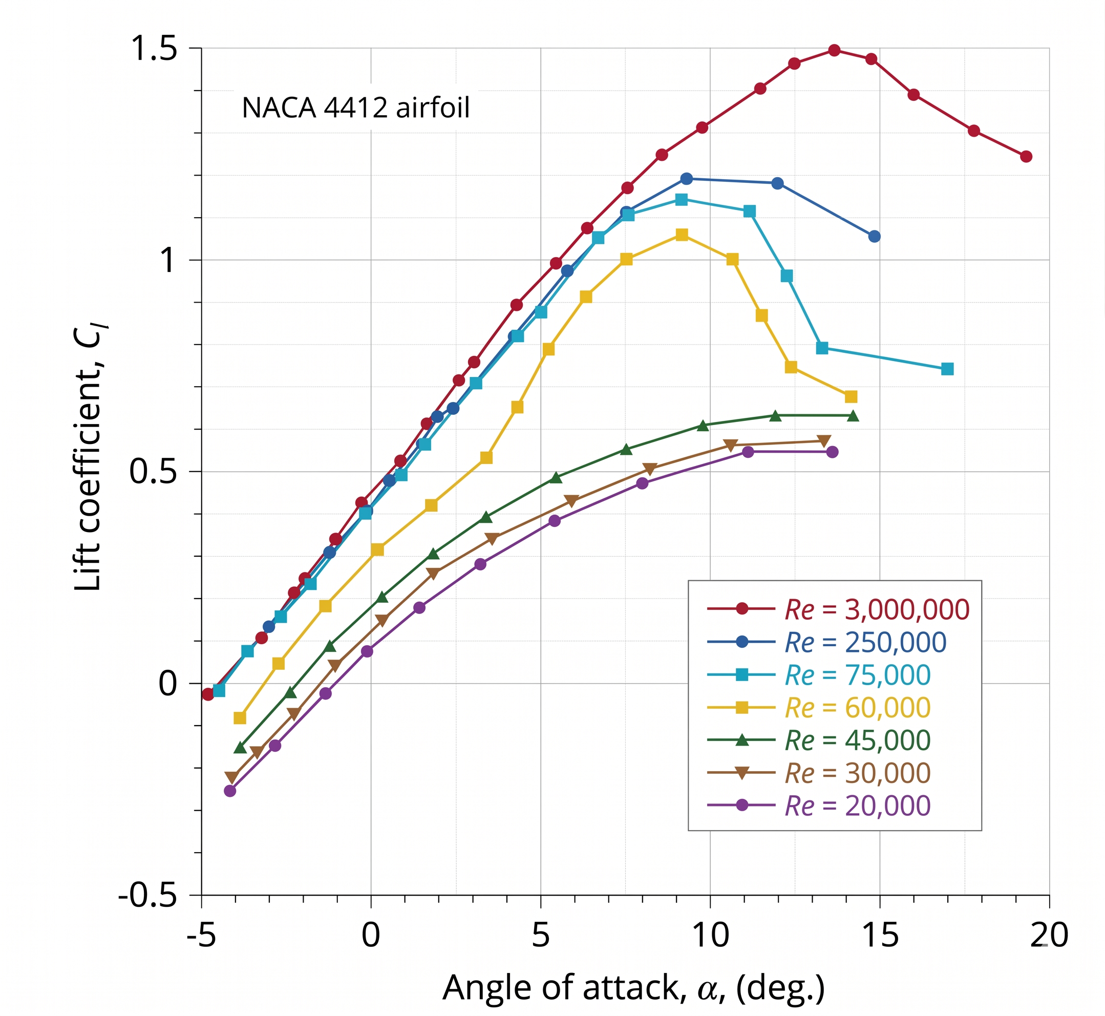
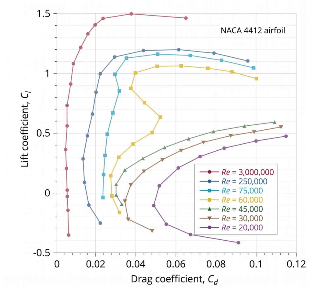
The Reynolds number has a large impact on the aerodynamic behaviour of a section. For low Reynolds Re<1e-6, the lift and drag curves become ever more rounded and eventually become completely non-linear. At higher Reynolds numbers, the boundary layer becomes more energized, stall is delayed and the lift becomes ever more linear. On the other hand, the drag becomes more independent of the angle of attack.
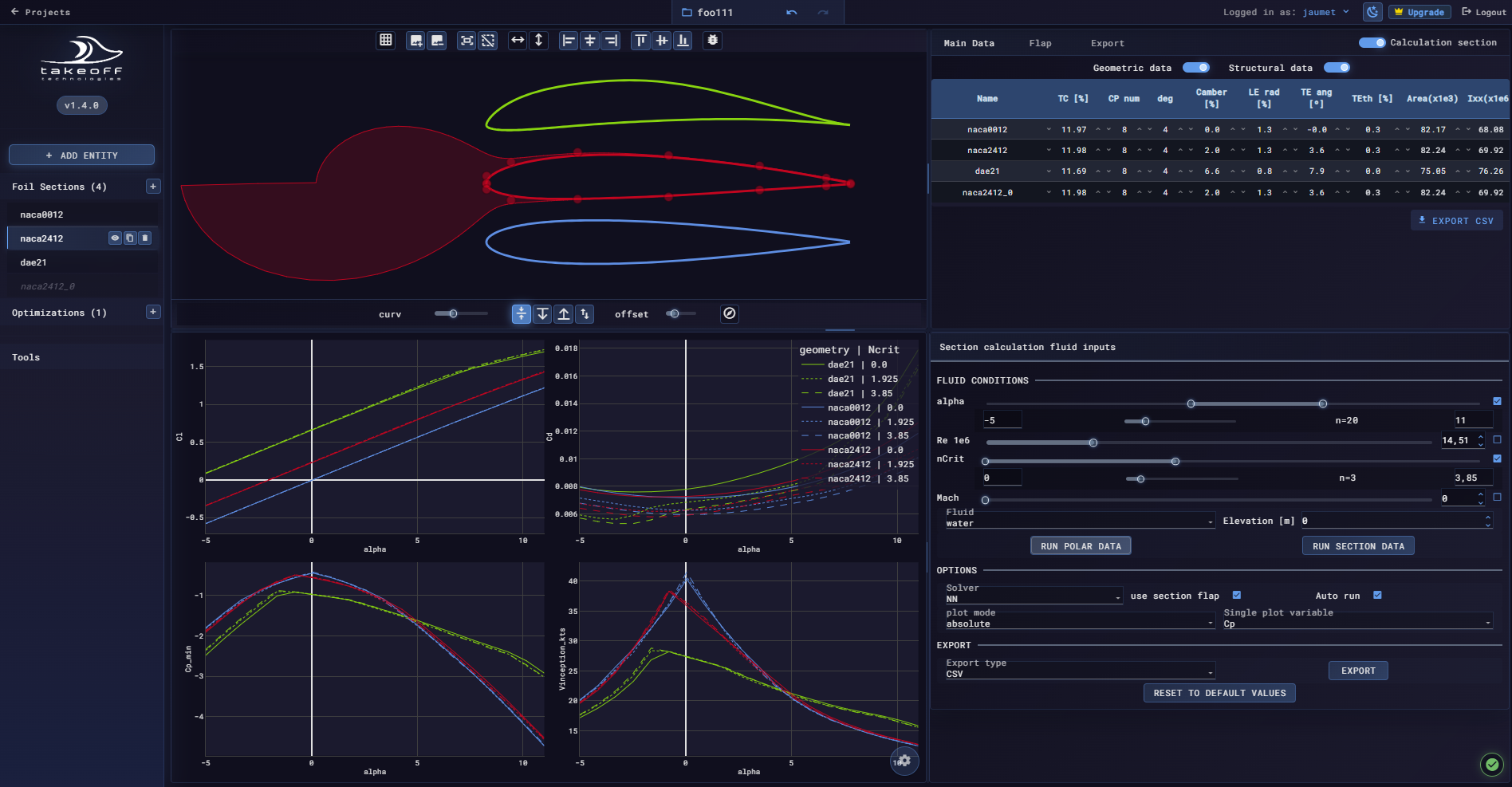
How does the TakeOff Tool help?
The TakeOff tool enables rapid exploration of the airfoil design space, helping engineers make informed decisions on aerodynamic trade-offs with confidence. Its real-time performance analysis allows users to instantly evaluate how geometric modifications affect each airfoil candidate as changes are made live.
By combining design, analysis, and optimization in a fast and intuitive workflow, TakeOff makes real-time airfoil development practical and accessible for the first time.